* This is a multi-part post. Here are links to all parts:
Part 1: Intro, bill of materials and simple sketch
Part 2: The 2-digit 7-segment display circuit; this post
Part 3: Sketch broken down in sections, explained
Part 4: Added two buttons, and modified sketch
Part 5: Code for buttons, explained
This week we’ll look at the circuit for the 2-digit 7-segment display counter using the Arduino.
There are a few options to control multiple displays:
- employing multiple controllers;
- using a 7-segment driver chip like the 7447;
- using a multi-display controller such as the MAXIM MAX7219;
- sequencing through the displays, which is what we have done in our example, as it requires no added hardware.
When we were using a single-digit display, we connected the common anode pin to our Vdd supply, but with two digits we have to drive them independently if we want them to display different digits!
A natural reaction would be to try to use two Arduino I/O pins, each driving a digit of the display. The problem with this scenario is that it is not possible to drive the common anode or cathode pin using Arduino I/O pins, as they cannot source or sink enough current to light all seven segments.
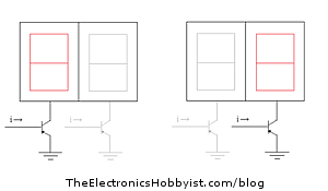
The solution is then to use bipolar junction transistors (NPN for common cathode and PNP for common anode displays) in order to sink or drive the required current. The controlling interface outputs the value for a specific display by enabling only its common pin transistor, and the digit driven by that common pin becomes active.
To give the impression that both displays are active at the same time and avoid flickering we cycle through the digits in quick succession and keep each of them lit for 5ms. We will see how that was implemented when we go over the sketch next week.
Here is the schematic for the 2-digit 7-segment display circuit (click for larger image):


 Arduino Protection: How to Make Sure Your Project Won’t Kill Your Arduino
 Motion and Light Sensors with Arduino (and Without)
 LED Patterns Using DIP Switch and Arduino
 Lumex Graphic LCD Road Test

Hi Natalia!
I just wanted to ask if I’m gonna use a common cathode 7-segment display,
will there be no changes other than the pin configuration?
Hi Jeanne, also pay attention that the transistors will be different for common cathode or common anode displays. As for the pins, you also have to follow the datasheet of your display, as the configuration may be different than the one I used. Good luck!
Hi there,im sherwin,im doing a project,but i have no idea how to code,it would be a great blessing if you could help me out please! My project would consist of a 1 digit 7 Segment display counter which counts from 0-9,and a switch to reset it to 0 and start it again.
I can only code until this far and i have no idea what to do next 🙁
Please help me,im really lost..
#define 7 SEGMENT_SL1 PORTBbits.RB2
#define 7 SEGMENT_SL2 PORTBbits.RB3
#define 7 SEGMENT_c PORTBbits.RB4
#define 7 SEGMENT_e PORTBbits.RB5
#define 7 SEGMENT_d PORTCbits.RC5
#define 7 SEGMENT_DP PORTCbits.RC6
#define 7 SEGMENT_g PORTAbits.RA0
#define 7 SEGMENT_b PORTAbits.RA1
#define 7 SEGMENT_f PORTAbits.RA2
#define 7 SEGMENT_a PORTAbits.RA3
Hi Sherwin, did you take a look at the previous single-digit display project? It was posted in 4 parts, here:
https://www.tinkerhobby.com/controlling-a-seven-segment-display-using-arduino-part-1-of-4/
https://www.tinkerhobby.com/controlling-a-seven-segment-display-using-arduino-part-2-of-4/
https://www.tinkerhobby.com/controlling-a-seven-segment-display-using-arduino-part-3-of-4/
https://www.tinkerhobby.com/controlling-a-seven-segment-display-using-arduino-part-4-of-4/
I’m really new to Arduino so forgive me if I’m missing something;
I can’t get the code to compile, the error reads
_2_digit_display.ino:50:38: error: ‘F’ was not declared in this scope
_2_digit_display.ino: In function ‘void setup()’:
_2_digit_display.ino:65:11: error: ‘F’ was not declared in this scope
Error compiling.
Can you help?
Hi Dave,
it means that in the old versions of the Arduino compiler we could use the identifier “F” in the define directive. Starting with version 1.0, Arduino defines a built-in function “F()” that allows you to store strings in flash memory.
From the Arduino release notes (https://arduino.cc/en/Main/ReleaseNotes):
“Support has been added for printing strings stored in flash (program memory) rather than RAM. Wrap double-quoted strings in F() to indicate that they should be stored in flash, e.g. Serial.print(F(“hello world”)).”
So sketches can no longer use “F” as an identifier, as it is now a reserved name. In other words: name “F” something else and the sketch will compile. For instance
#define F_segment 4
You can also read the comments on this post: https://www.tinkerhobby.com/controlling-a-seven-segment-display-using-arduino-part-4-of-4/
Hi
how i can use double 7seven segment (common cathode) Display with Pic micro-controller
Please suggest me simplest possible circuit.
i want to show 65 ,73 etc digits
Hi Asif,
I don’t have much experience with PICs, sorry!