* This is a multi-part post. Here are links to all parts:
Part 1: Overview and bill of materials
Part 2: Assembly
Part 3: DC motor control
Part 4: RGB LED control, this post
When looking at the parts list for the Arduino RGB LED spinning night light you must have noticed that current limiting resistors of different values were used for the Red and the Green/Blue pins of the RGB LED. That is due to them having different forward voltage ratings. You can find complete specs for the LED in the datasheet (when buying an electronic component you will have the option to download its datasheet, or the relevant information will be provided by the vendor).
We use Ohm’s Law to calculate current limiting resistor values:
Forward voltage ratings:
RED: 2.1V
GREEN: 3.3V
BLUE: 3.3V
Current:
I = 20mA
Supply voltage:
V = 5V
Ohm’s Law:
I = V/R => R = V/I
So for Red:
(5 – 2.1)/0.02 => R = 145 Ohm
For Green/Blue:
(5 – 3.3)/0.02 => R = 85 Ohm
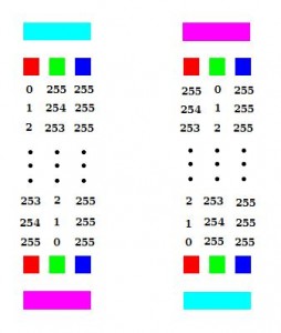
 As for the Arduino sketch, I chose to have the lamp fade between two colors, aqua (#00FFFF) and magenta (#FF00FF). For that I kept the Blue value at 255 and varied the Green and Red values between 0-255 to achieve the desired colors, as shown in the diagram:
(You can pick your favorite colors, cycle through the entire spectrum, or go psychedelic and show random colors with random delays)
// fade from aqua to magenta
  for (int i = 0; i < 256; i++) {
    analogWrite(RED, 255-i);
    analogWrite(GREEN, i);
    analogWrite(BLUE, 0);
    delay(50);
  }

  // fade from magenta to aqua
  for (int i = 0; i < 256; i++) {
    analogWrite(RED, i);
    analogWrite(GREEN, 255-i);
    analogWrite(BLUE, 0);
    delay(50);
  }
Here’s the full sketch for the night light.

 Arduino Protection: How to Make Sure Your Project Won’t Kill Your Arduino
 Phase 0 of the IPON Project
 Motion and Light Sensors with Arduino (and Without)
 LED Patterns Using DIP Switch and Arduino
