A while ago I purchased an Ardweeny kit, but hadn’t put it together and tested it until now. The Ardweeny is a small, low-cost breadboard friendly Arduino clone. In fact, it is the smallest Arduino clone that I know of as of this posting, and the tiny board is backpacked on top of the ATMega chip.

Here are the parts laid out before I put the Ardweeny together: PCB, ATMega, headers and 7 parts. Tip: double check that you received the correct parts; I received a 470K Ohm resistor (yellow-violet-yellow) instead of a 470 Ohm (yellow-violet-brown) one.
[continue reading…]
 If you’ve read Getting Started with Arduino you must have noticed that the circuit on page 43 uses a 10K Ohm resistor in series with the push-button. (If you haven’t read it yet, the example in the schematic on the right is similar to the setup featured on the book).
Consider a microcontroller with a digital input pin connected to a switch. When the switch is closed, the pin is connected to GND. When the switch is open, the signal is not connected to anything and is left at an unknown state. The signal is in this case said to be “floating”. This is pictured in circuit (1).
To remedy this problem we pull the signal up to VCC, as shown in circuit (2). Now when the switch is open the signal is connected directly to VCC and is at a known state. But notice that when the switch is closed, VCC and GND are connected, creating a short.
[continue reading…]
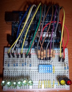
This is an addendum to the LED control using DIP switch post, to include the schematic to the project circuit:

 This is a very simple project that controls a set of LEDs using a DIP switch. The purpose of the sketch is to show the use of some Arduino serial communication functions, and to increase familiarity interfacing with digital I/O pins.
(Here is the schematic for this project)
Two LEDs were connected to the RX and TX pins on the Arduino (digital pins 0 and 1), but remember to disconnect these pins while the sketch is being uploaded.
Parts list:
- Arduino Duemilanove (or Arduino Uno)
- Breadboard
- 8 LEDs, assorted colors (or you can also get a grab bag of assorted types and colors)
- Jumper wire, assorted lengths
- DIP switch
- 6 10K Ohm resistors (pull up)
- 8 100 Ohm resistors (current limiting)
Computers can exchange bits of information serially (one after another, in sequence) or in parallel (several at the same time). In applications where it is necessary to have one computer talk to another, the most commonly used communication method is serial.
So it is no surprise that serial communication is the method used to send data between the Arduino board and a computer (or other device). Information is sent to and from the computer and the Arduino by setting a pin high or low. One side sets the pin and the other reads it.
The Arduino Duemilanove Board has one serial port that communicates on digital pins 0 (RX) and 1 (TX) as well as with the computer via USB. When you use the IDE to Upload your sketches to the Arduino, the bits are transmitted one at a time through the USB cable to the Arduino. The serial connection can also be used in our sketches to send data to the computer and to receive data from the computer via the serial monitor available on the IDE. This proves very useful for debugging your projects, as we will explore in the upcoming posts.
[continue reading…]
* This is a multi-part post. Here are links to all parts:
Part 1: Overview and bill of materials
Part 2: Assembly
Part 3: DC motor control
Part 4: RGB LED control, this post
When looking at the parts list for the Arduino RGB LED spinning night light you must have noticed that current limiting resistors of different values were used for the Red and the Green/Blue pins of the RGB LED. That is due to them having different forward voltage ratings. You can find complete specs for the LED in the datasheet (when buying an electronic component you will have the option to download its datasheet, or the relevant information will be provided by the vendor).
We use Ohm’s Law to calculate current limiting resistor values:
[continue reading…]


